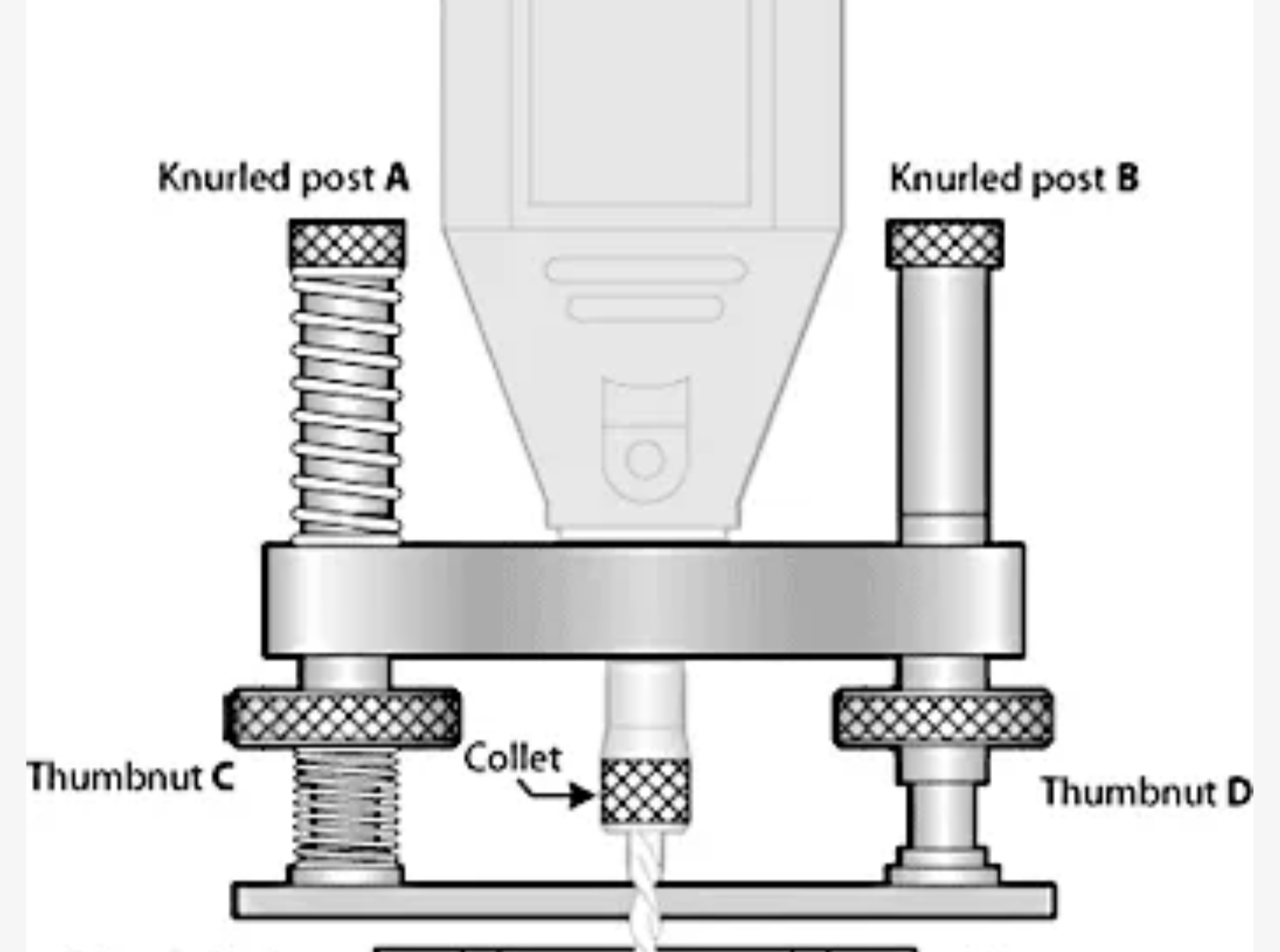
I am taking a weekend course in six days on inlay. The course tool list includes either a laminate router or a rotary tool with base. I have always wanted a base for the Dremel, but it is too late to order one from StewMac, so I will make a copy of the StewMac router base. The schematic for this router base is shown in the screenshot below.
I checked dimension in the screenshot above and compared them with the Dremel neck size. The plan below shows the sizes of the five parts to be made. I have some 2" long 1/4-20 screws that might be long enough. I found a sheet of 3/16" aluminum for the base and a block of 1/2" thick aluminum for the rotary tool holder. This part will be made like the rotary clamping tool made a few years back, with a threaded brass insert.
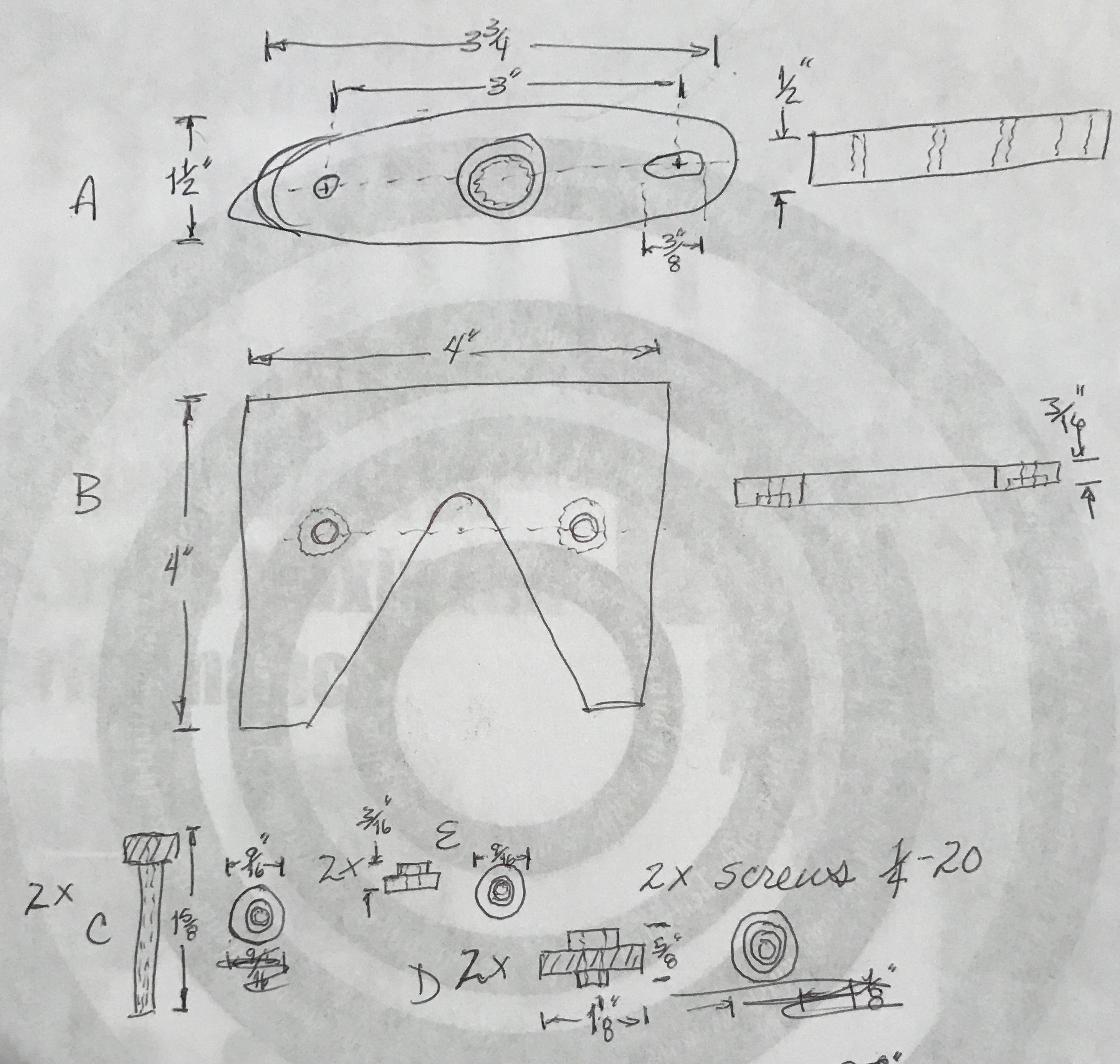
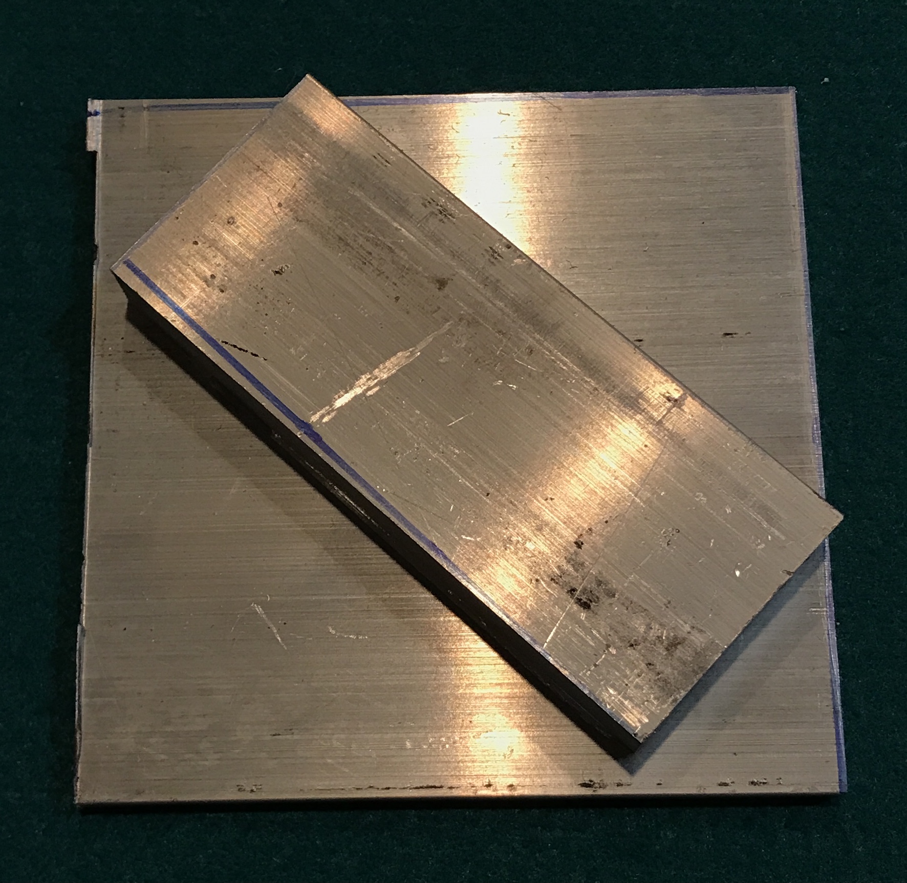
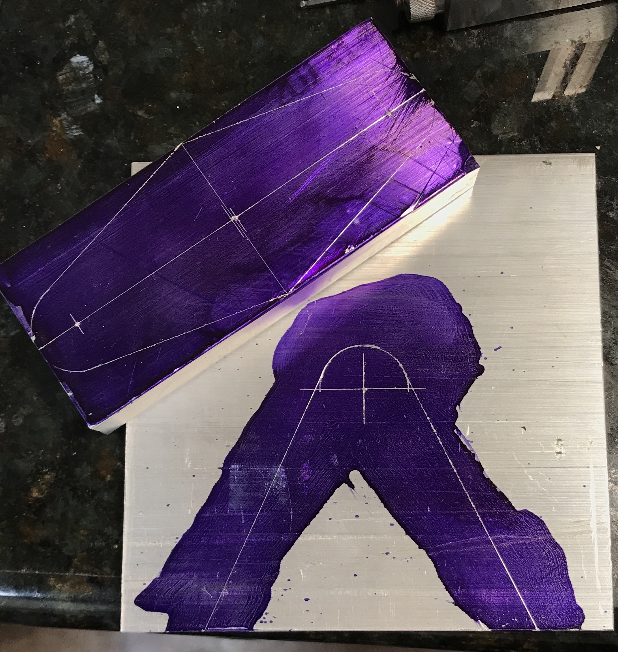
The first task is cutting off aluminum pieces for the base and the holder. The pieces were cut to rough shape on the horizontal bandsaw. The first photo below shows the two parts cut to rough size. They were cut to square on the mill. The centers of holes and the cutting lines were laid out on the two parts. This can be seen in the second photo below. The only dimension marked out, but not included in the plan above is the legs on the base. They start 5/8" in from the sides and are tangent to the 3/4" circle centered in the part.
The holes in the holder need to be drilled prior to trimming the part to the scribed lines for ease of holding. The two holes on the ends need to fit a 1/4" screw, while the central hole will have the threaded bushing for the Dremel. The last time I made such a bushing for the Dremel the bushing was 1" in diameter, bored to 0.665" and 3/4-12 threads were cut on the Sherline. Consequently I need a 1" hole in the center of this holder.
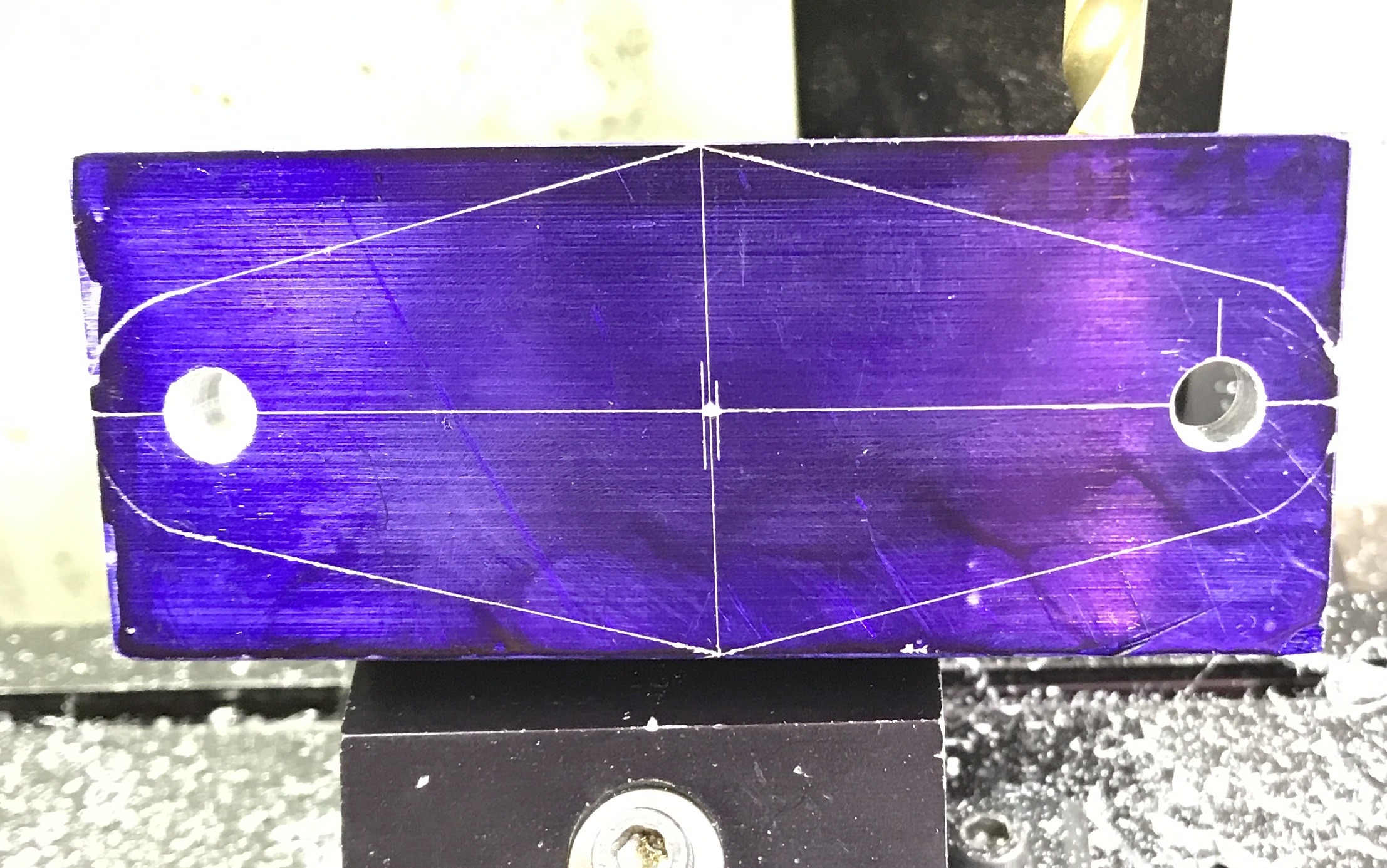
The two holes in the holder were drilled up to an "F" drill, 0.257". They were lightly chamfered. The photo below shows the holder at this stage. One of these holes needs to be slightly widened with an end mill. That work will need to wait until Rhea is out of the house as I expect it to be noisy.
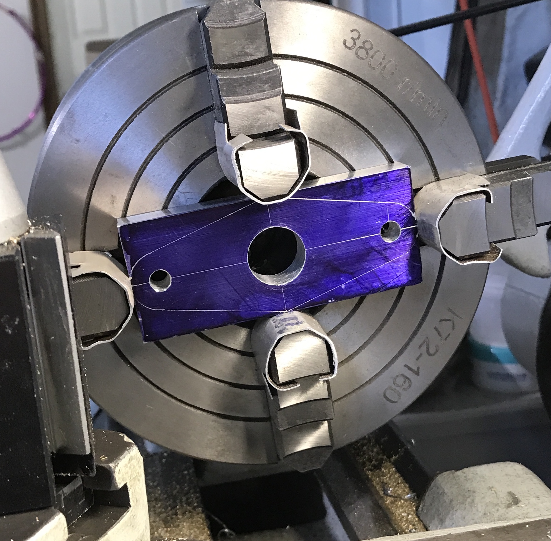
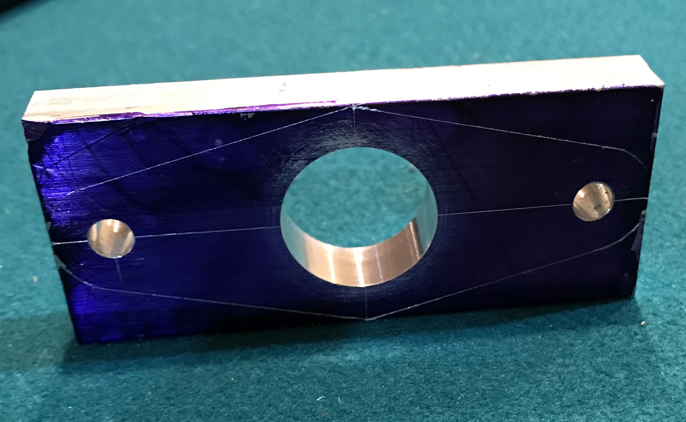
The holder was moved to the four jaw chuck on the South Bend. It was first centered with the tailstock center. Then it was centered drilled and drilled up to 3/4" as seen in the first photo below. The boring bar was installed and the hole was opened to 0.992". The bored part is shown below in the second photo.
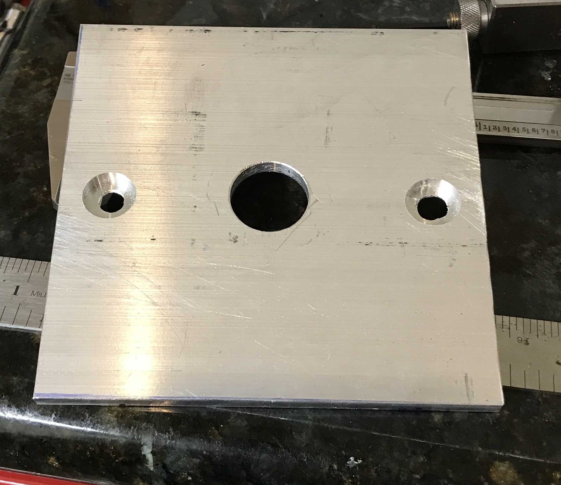
The center line of the base was extended to both sides for eventual alignment with the holder. The plate was centered in the four jaw chuck in the South Bend lathe. The plate was center drilled and then drilled up to 3/4". The photo shows the hole drilled in the plate. (The plate is held up with the cue ball from the kid's pool table.)
The holder was aligned with the base so its holes were centered over the line scribed on the base. The two were clamped together and the holes were transferred. The holes were then drilled in the base again up to an "F" drill. The bolts were an easy fit in the two holes as seen in the photo below. One hole was stretched with a 1/4" end mill. The hex heads on the bolts are 1/2", so that is the size of the needed countersink.Both holes were countersunk with first a 3/8" end mill followed with a 1/2" end mill. The "stretched" hole also had the countersink stretched with the 1/2" end mill. The second photo below shows the countersinks. The heads of the bolts are just a bit proud and need to turned down, which they were.
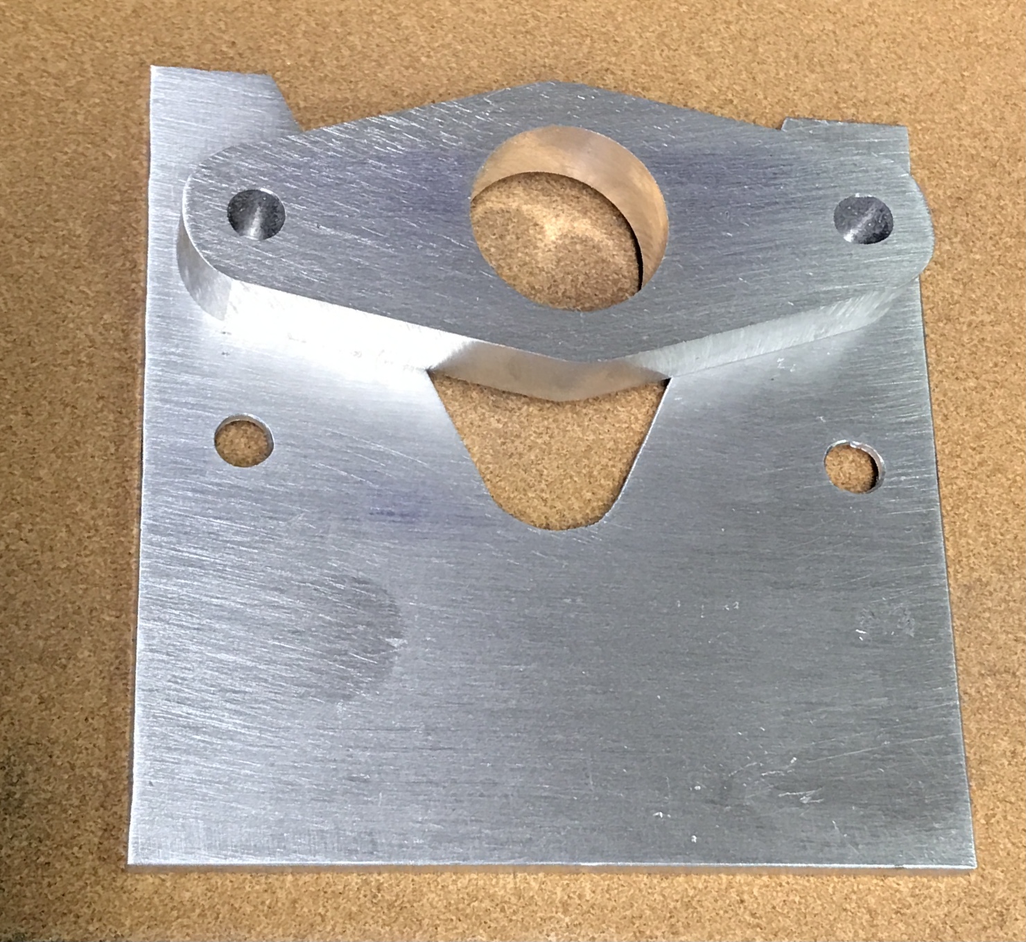
The base was held in the vise with one of the angled lines vertical. A cut was made along the line to the hole with a hacksaw. This was repeated for the other angled line freeing the waste. The sawn edges were filed smooth and both sides of the base were sanded with 120 grit sandpaper. Wedges were cut from the holder with a hacksaw. After attempting to file the piece to the lines in the 85° garage, the part was moved to the basement. The table was setup on the belt sander and the part was sanded to the lines. Water was poured into a baggie and this was used to intermittently cool the part, which grew too hot to hold. Both faces of this part were also sanded with 120 grit paper. The photo below shows the two finished parts.
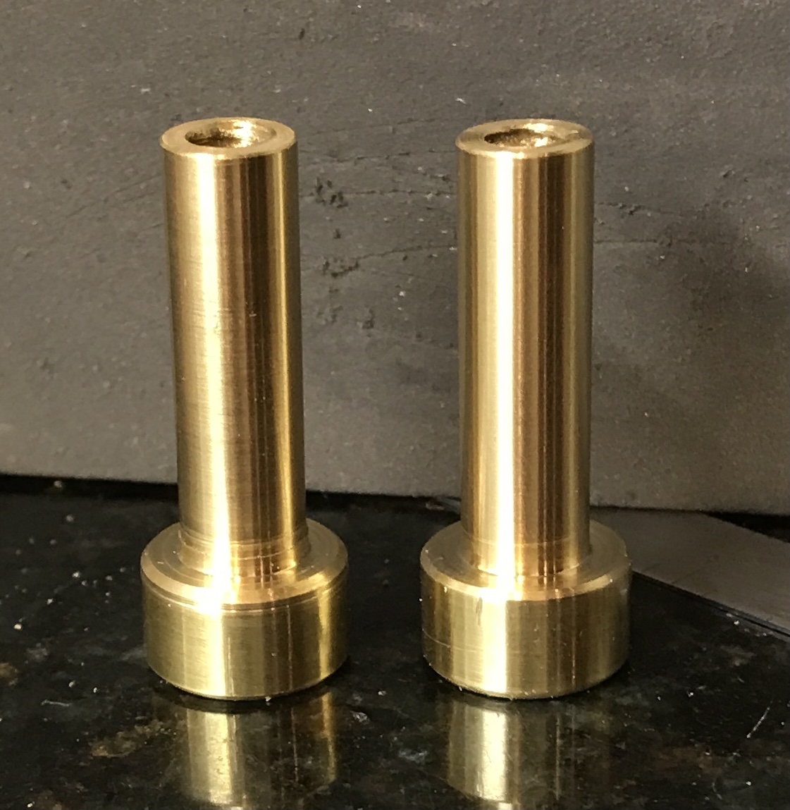
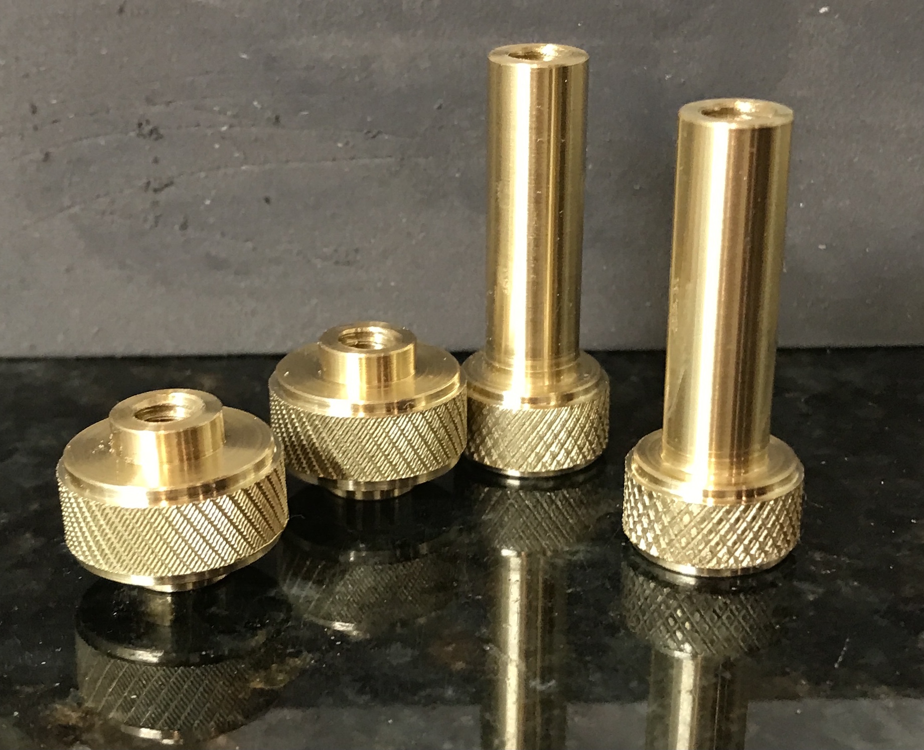
The upper nuts (labelled C in the plan above) were made next. Two 1 5/8" lengths of 5/8" brass round were cut off with a hacksaw. One was put in the three jaw chuck and both ends were faced. About 1/4" was held in the chuck and the distal end was center drilled. A tailstock center was put in place and 1 1/4" was reduced to 3/8". The part was drilled about 1 3/8" deep with a #7 drill and threaded 1/4-20. The underside of the large section was cleaned up in the lathe and the large section was polished with crocus cloth. The photo below shows the two parts finished except for knurling.
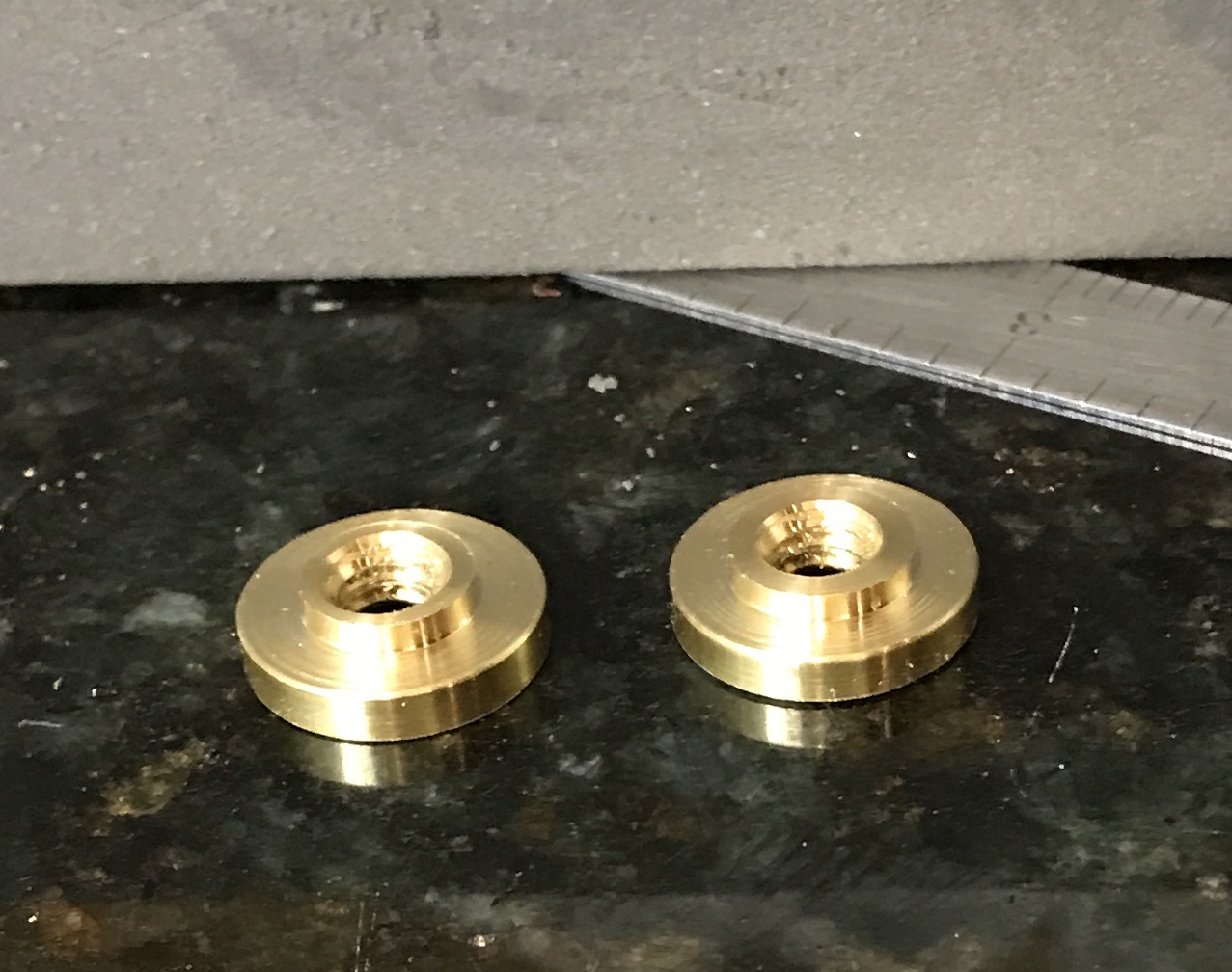
The bottom nuts were next to be done. A short length of 5/8" brass round was cut off. It was center drilled and drilled with an "F" drill. It was tapped 1/4-20. 1/16" was reduced to 3/8" and a nut was parted off 1/8" further on. A nasty burr was hard to remove. This was repeated producing the two nuts seen in the photo below. The second photo shows the device at this stage.
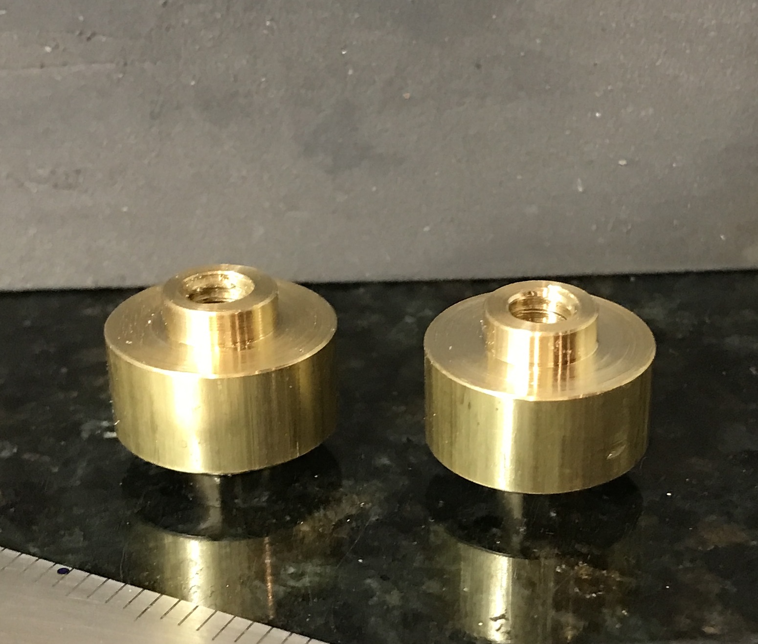
The middle nuts were made 5/8" long from 3/4" brass round stock. Two pieces were cut from the stock with a hacksaw slightly longer than 5/8". They were faced on both sides. Each side of both pieces was reduced for 1/8" to 3/8" diameter. The corners were chamfered. Both were center drilled and drilled through with a #7 drill. The holes were threaded 1/4-20. The two middle nuts at this stage are shown in the photo below.
After completing the three nuts the middle and top nuts need knurls. The lathe was setup to do knurling with the knurl holder held in the QCTP. The smaller top nuts were knurled first and both came out with well formed knurls. A lot of cutting fluid was used. The middle nuts were screwed onto a screw and held tightly against the screw head with a nut. The screw was held in a 1/4" collet. This knurl was more difficult to form due to the larger diameter of the material. I could not run the knurling tool onto the end of the brass. Instead it was centered over the brass and then tightened. The edges of the knurls were not great looking, so these were removed 0.050" wide and 0.030" deep. The resulting corners were lightly chamfered. The photo below shows the completed knurls and the difference between the smaller and the larger.
The last part to make is the brass bushing. The hole in the holder is 0.991". A press fit into this hole is the first target. To that end a 1" length of 1" brass round was cut off with the hacksaw. The bushing was reduced for 1/2" to 0.992" and was a slip fit in the holder! The holder was measured three times all three showed 0.991" diameter. I must be using the hole gauges incorrectly. The part was faced and drilled to 3/8" in the Sherline lathe. It was then moved to the South Bend and drilling continued up to 5/8". It was bored to 0.665.
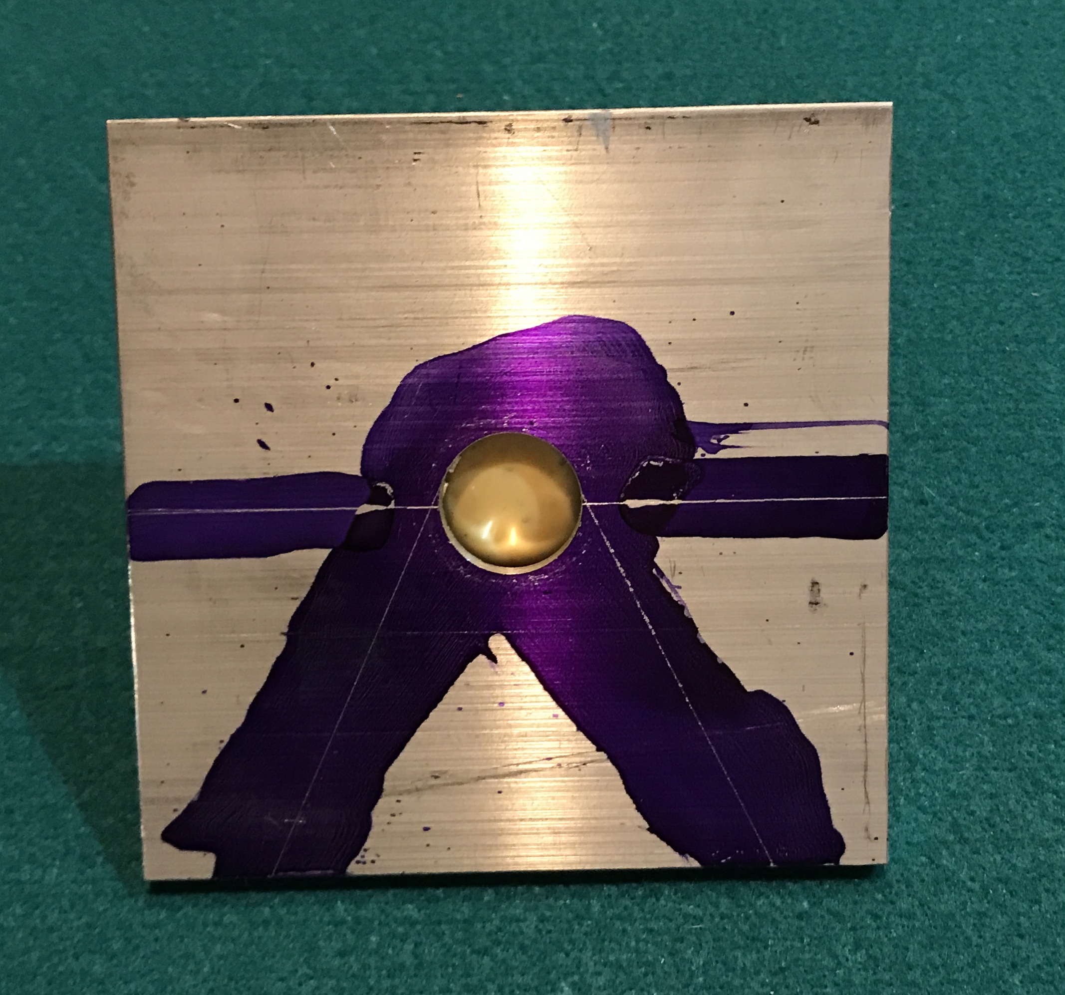
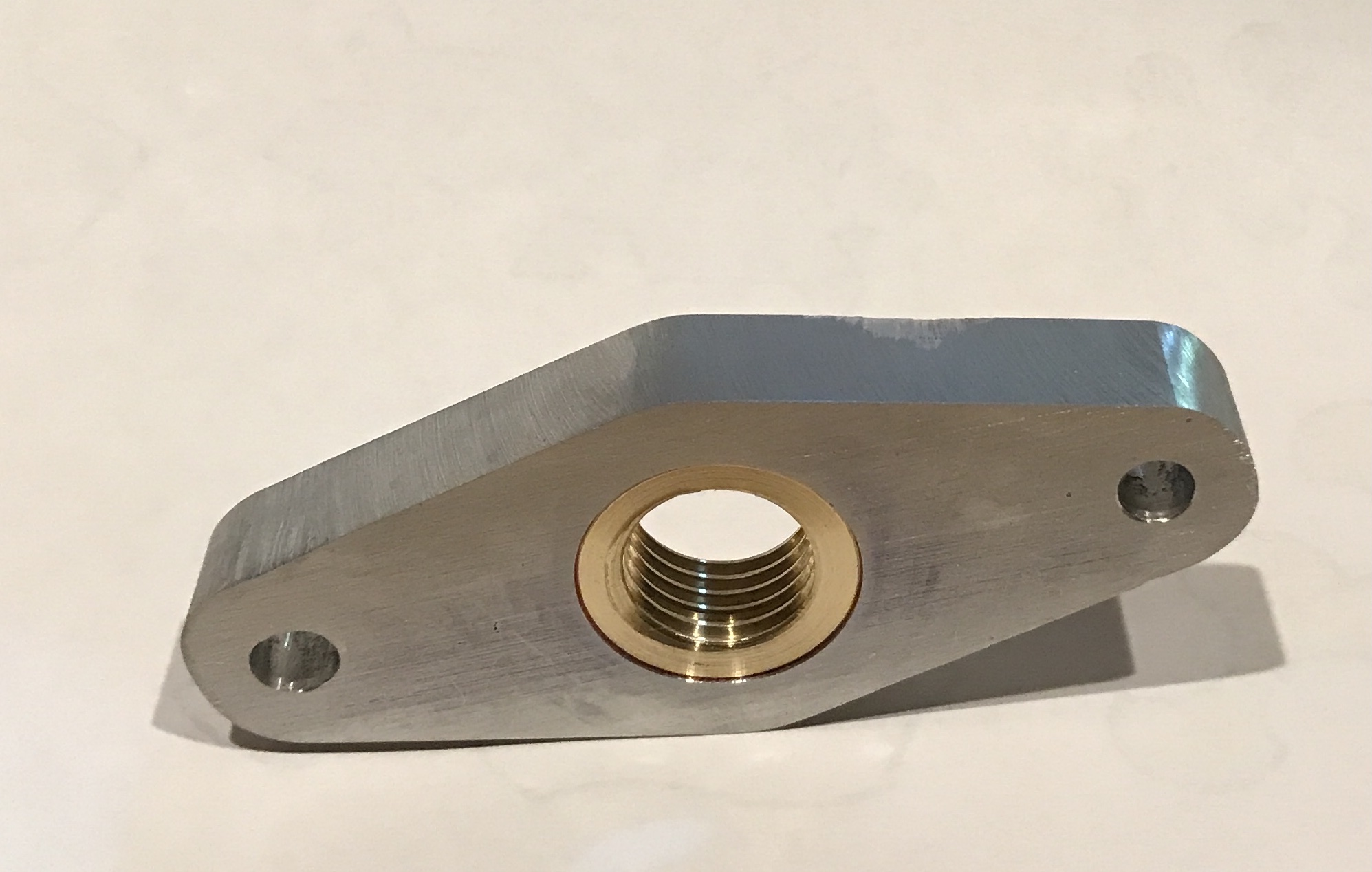
It was returned to the Sherline and the lathe was set up for threading. The bushing was threaded 3/4-12 to fit the Dremel rotary tool. The threading went well up to about 0.050" deep, then it became very slow, advancing in 0.0005" increments. The Dremel was tested at 0.058" nominal thread depth and fit, so the plan to go to 0.065" was shelved. The bushing was parted off and glued applied after wiping both mating surfaces with acetone. The bushing did not slip into the holder! It required the vise in the garage to press it into place. It was slightly warm from parting off, but I can't imagine that was the difference. The photo below shows the holder with bushing in place.
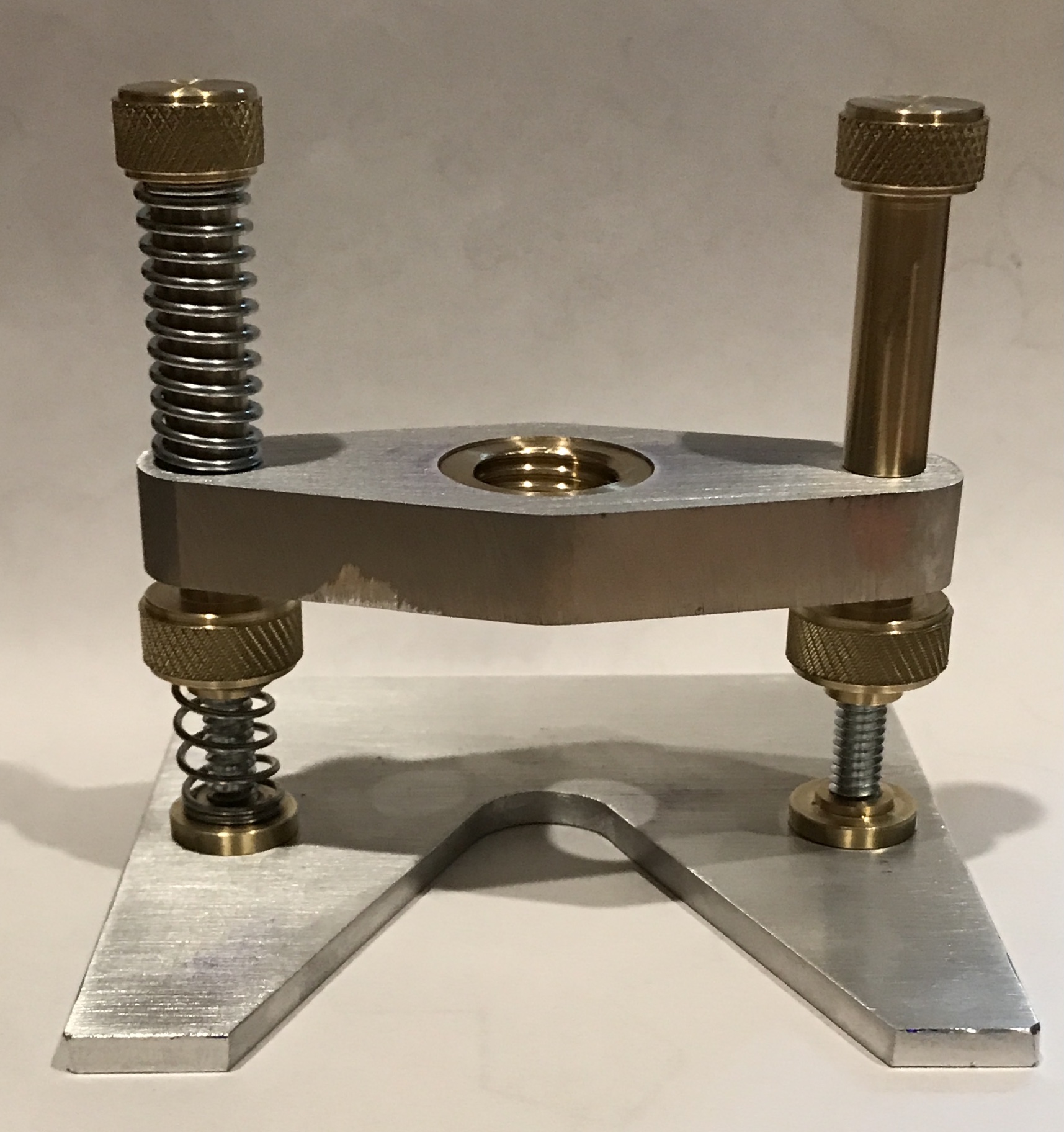
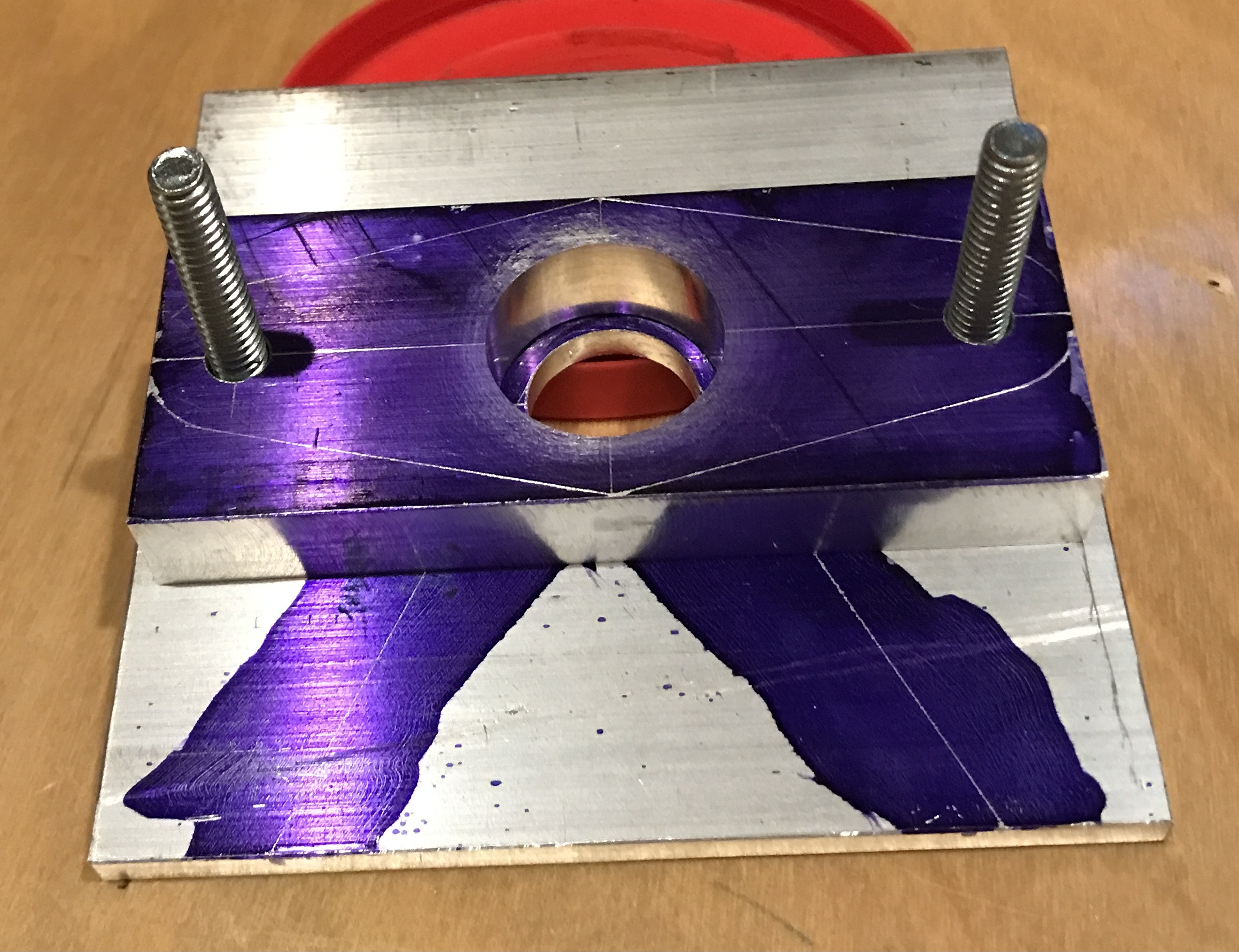
The jig is shown with two springs. I will fish through my stock of springs to see if there are matches (3/8" ID and 8 or 10 coils). If not, I can always make them. The bottom nuts also need to be glued in place. The nine parts were assembled and can be seen in the photo below.
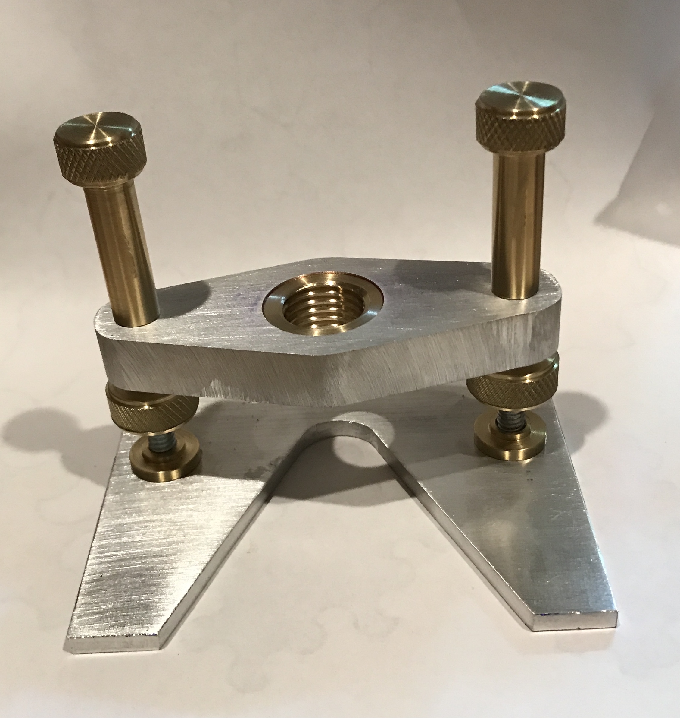
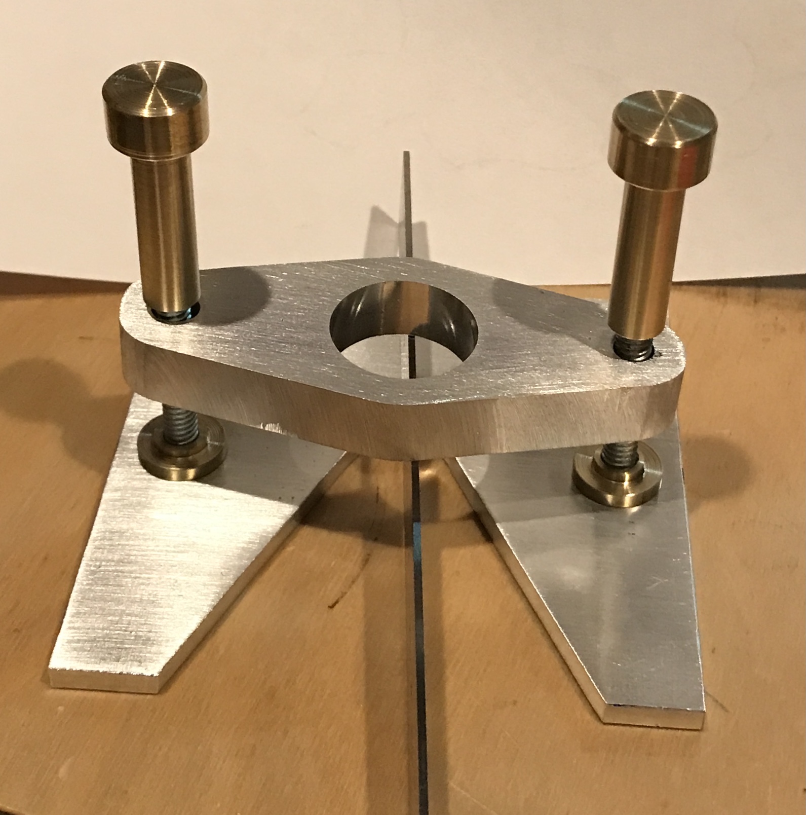
A few remaining items were taken care of to complete the jig. The corners on the base were lightly chamfered with a file. A 1/2" X 1 1/2" spring was purchased from Menards. Two 3" screws were also purchased, shortened to 2 1/2", and the heads thinned to fit in the countersink. The bottom screws were affixed to the installed screws with Loctite. The fully complete rotary tool base is shown below.